Introduction
Hardware-accelerated ray tracing was one of the most innovative additions to the next-generation APIs (Direct3D12 and Vulkan) of the recent years. It unlocks a wide range of algorithms that are impossible or very tricky to implement in a traditional rasterization pipeline. However, ray tracing API in both Direct3D12 and Vulkan is quite involved and is not always easy to follow.
Diligent Engine is a modern cross-platform low-level graphics library and rendering framework that supports multiple rendering backends including Direct3D12 and Vulkan. Please refer to this article for the introduction to this project. In a most recent release, Diligent Engine enabled support of hardware-accelerated ray-tracing through a common easy-to-use yet fully exhaustive API. Ray tracing shaders authored in HLSL will work in both backends without any special tricks or hacks. Shaders written in GLSL as well as compiled SPIRV bytecode can also be used in Vulkan backend.
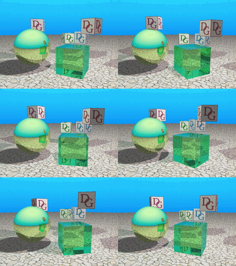
This article gives an introduction to ray tracing API in Diligent Engine by the example of a simple application that simulates physics-based light transport in a scene to render soft shadows, multiple-bounce reflections and refractions, and dispersion.

Ray Tracing vs Rasterization
In a traditional rendering pipeline, triangles are processed by a number of programmable and fixed-function stages and are eventually projected and rasterized over the regular pixel grid. The final color is formed by a pixel shader and a number of optional blending operations. This is a very efficient and high-performance method, but performance comes for the price of a number of limitations. First, the pixel shader can only be invoked for the predefined sample locations (which enables GPUs to parallelize the execution very efficiently). Second, the GPU does not have access to the whole scene and only triangles visible by the camera are processed.
Ray tracing removes these limitations. Unlike the rasterization, it allows application to query scene properties at any location by casting a ray in any direction and running a specified shader at the intersection point.
Acceleration Structures
Unlike rasterization, where objects do not require any pre-processing and can be thrown into the pipeline rightaway, things are a bit more complicated in ray tracing. Since a ray can be cast in any direction, the GPU must have an efficient way of intersecting the ray with the entire scene. This way is provided by acceleration structures that typically encompass some kind of bounding volume hierarchies.
There are two types of acceleration structures (AS) in ray tracing API: bottom-level AS, and top-level AS. Bottom-level acceleration structure (BLAS) is where the actual geometry resides. Top-level acceleration structure is a set of references to one or more BLASes. One TLAS may reference multiple instances of the same BLAS with different transformations. BLASes are more expensive to build or update than TLASes. The two-level structure is a trade-off between the ability to update the AS at run-time and ray tracing efficiency. For example, object animation can be implemented by updating instance transformations in the TLAS without the need to rebuild BLASes that represent animated objects.
Bottom-level Acceleration Structures
There are two types of geometries that a BLAS can contain: triangle geometry or procedural. Triangle geometry is represented by a conventional set of vertices and indices. Procedural geometry requires an application to define a special type of shader that determines how a ray intersects the object. That shader can implement any custom algorithm, but is more expensive than a built-in ray-triangle intersection test.
A single BLAS may contain only one type of geometry: either triangles or axis-aligned bounding boxes (AABBs) that define the basic procedural object shape.
In this example we will be using two types of objects: a cube and a sphere. The cube will be defined by a triangle geometry, while the sphere will be defined as a procedural geometry. The cube data will be accessed through a uniform buffer (rather than traditional vertex/index buffers), so that a closest hit shader can read triangle properties (position, normal, UVs) for any primitive.
For our cube BLAS, we specify a single triangle geometry with 24 vertices and 12 primitives. The BLAS will allocate space that is enough for this geometry description:
const float3 CubePos[24] = /* ... */;
const uint   Indices[36] = /* ... */;

BLASTriangleDesc Triangles;
Triangles.GeometryName         = "Cube";
Triangles.MaxVertexCount       = _countof(CubePos);
Triangles.VertexValueType      = VT_FLOAT32;
Triangles.VertexComponentCount = 3;
Triangles.MaxPrimitiveCount    = _countof(Indices) / 3;
Triangles.IndexType            = VT_UINT32;

BottomLevelASDesc ASDesc;
ASDesc.Name          = "Cube BLAS";
ASDesc.Flags         = RAYTRACING_BUILD_AS_PREFER_FAST_TRACE;
ASDesc.pTriangles    = &Triangles;
ASDesc.TriangleCount = 1;

m_pDevice->CreateBLAS(ASDesc, &m_pCubeBLAS);
Note that in this example, GeometryName member is not used anywhere else except in BLAS build. In other cases, however, the geometry name may be used to change the geometry data using the BLAS update operation. Geometry name may also be used in a shader binding table as described below.
The cube BLAS is now created, but contains no data: we need to initialize it. For that, we will need to create regular vertex and index buffers, with the only difference that we will use the BIND_RAY_TRACING flag to allow access to the buffers during the BLAS build operation. All buffers which are used in the BLAS or TLAS build commands must be created with BIND_RAY_TRACING flag. The GPU needs some scratch space to perform the build operation and keep temporary data, which must be provided to BuildBLAS command. Call m_pCubeBLAS->GetScratchBufferSizes() to get the minimal scratch buffer size.
BLASBuildTriangleData TriangleData;
TriangleData.GeometryName         = Triangles.GeometryName;
TriangleData.pVertexBuffer        = pCubeVertexBuffer;
TriangleData.VertexStride         = sizeof(CubePos[0]);
TriangleData.VertexCount          = Triangles.MaxVertexCount;
TriangleData.VertexValueType      = Triangles.VertexValueType;
TriangleData.VertexComponentCount = Triangles.VertexComponentCount;
TriangleData.pIndexBuffer         = pCubeIndexBuffer;
TriangleData.PrimitiveCount       = Triangles.MaxPrimitiveCount;
TriangleData.IndexType            = Triangles.IndexType;
TriangleData.Flags                = RAYTRACING_GEOMETRY_FLAG_OPAQUE;

BuildBLASAttribs Attribs;
Attribs.pBLAS             = m_pCubeBLAS;
Attribs.pTriangleData     = &TriangleData;
Attribs.TriangleDataCount = 1;
Attribs.pScratchBuffer    = pScratchBuffer;

m_pImmediateContext->BuildBLAS(Attribs);
Note that GeometryName member of BLASBuildTriangleData struct instance must match the geometry name used in BLASTriangleDesc. When BLAS contains multiple geometries, this is how triangle data is mapped to the specific geometry in the BLAS.
Creating BLAS for procedural sphere is performed in a similar fashion.
Top-level Acceleration Structure
Top-level acceleration structure represents the entire scene and consists of multiple BLAS instances.
To create a TLAS, we only need to specify the number of instances it will contain:
TopLevelASDesc TLASDesc;
TLASDesc.Name             = "TLAS";
TLASDesc.MaxInstanceCount = NumInstances;
TLASDesc.Flags            = RAYTRACING_BUILD_AS_ALLOW_UPDATE |
                            RAYTRACING_BUILD_AS_PREFER_FAST_TRACE;
m_pDevice->CreateTLAS(TLASDesc, &m_pTLAS);
Additional flags tell the system how the structure will be used by the application:
RAYTRACING_BUILD_AS_ALLOW_UPDATE flag allows the TLAS to be updated after it has been created with different instance transformations;
RAYTRACING_BUILD_AS_PREFER_FAST_TRACE flag tells the GPU to make some optimization to improve ray tracing efficiency, for the price of extra build time.
Similar to BLAS, a new TLAS contains no data and needs to be built. To build a TLAS, we need to prepare an array of TLASBuildInstanceData structs, where every element will contain the instance data:
Instances[0].InstanceName = "Cube Instance 1";
Instances[0].CustomId     = 0; // texture index
Instances[0].pBLAS        = m_pCubeBLAS;
Instances[0].Mask         = OPAQUE_GEOM_MASK;

Instances[1].InstanceName = "Cube Instance 2";
Instances[1].CustomId     = 1; // texture index
Instances[1].pBLAS        = m_pCubeBLAS;
Instances[1].Mask         = OPAQUE_GEOM_MASK;
AnimateOpaqueCube(Instances[1]);

...

Instances[5].InstanceName = "Sphere Instance";
Instances[5].CustomId     = 0; // box index
Instances[5].pBLAS        = m_pProceduralBLAS;
Instances[5].Mask         = OPAQUE_GEOM_MASK;

Instances[6].InstanceName = "Glass Instance";
Instances[6].pBLAS        = m_pCubeBLAS;
Instances[6].Mask         = TRANSPARENT_GEOM_MASK;
The InstanceName member is used in TLAS update operation to match the instance data to the previous instance state and is also used in the shader binding table to bind the shader hit groups to the instances.
Hit shader can query the instance index in the array via InstanceIndex() function. CustomId
member is specified by the user and is passed to the hit shader via InstanceID() function.
CustomId may be used to apply different materials to each instance with the same geometry.
Mask can be used to group instances and trace rays only against selected groups (e.g. shadow rays vs primary rays).
For each instance, we can specify a transformation matrix with the rotation and translation, e.g.:
Instances[6].Transform.SetTranslation(3.0f, 4.0f, -5.0f);
Updating the instance transformation during the TLAS update operation is much faster than
updating BLAS with vertex transformation or using the transform buffer.
To build/update TLAS, we need to prepare an instance of BuildTLASAttribs struct:
BuildTLASAttribs Attribs;
Attribs.HitGroupStride = HIT_GROUP_STRIDE;
Attribs.BindingMode    = HIT_GROUP_BINDING_MODE_PER_INSTANCE;
HitGroupStride is the number of different ray types. In this example we use two ray types: primary and shadow. You may add more ray types, e.g. a secondary ray that uses simplified hit shaders for reflected rays.
BindingMode is the hit group location calculation mode. In our example we will be assigning different hit groups to different instances, so we use the HIT_GROUP_BINDING_MODE_PER_INSTANCE mode. If an application needs more control, it can use HIT_GROUP_BINDING_MODE_PER_GEOMETRY mode to assign indiviudal hit group to each geometry within every instance. On the other hand, it can use HIT_GROUP_BINDING_MODE_PER_TLAS mode to assign the same hit group to all geometries in all instances.
The actual TLAS instance data is stored in an instance buffer. The required size per one instance is fixed and is given by TLAS_INSTANCE_DATA_SIZE constant (64 bytes).
Similar to BLAS build operation, the GPU requires a scratch buffer to keep temporary data.
The required scratch buffer sizes for building and updating is given by m_pTLAS->GetScratchBufferSizes() method.
Attribs.pInstances      = Instances;
Attribs.InstanceCount   = _countof(Instances);
Attribs.pInstanceBuffer = m_InstanceBuffer;
Attribs.pScratchBuffer  = m_ScratchBuffer;
Attribs.pTLAS           = m_pTLAS;
m_pImmediateContext->BuildTLAS(Attribs);
Ray-Tracing Pipeline State
Ray-tracing pipeline state object is more complex than a graphics or a compute pipeline as there may be multiple shaders of the same type in one shader stage. This is required so that the GPU can run different shaders when hitting different objects.
Similar to other pipeline types, we start by creating all shaders that will be used by the ray tracing pipeline. Diligent Engine allows using HLSL for both D3D12 and Vulkan backends. The minimum HLSL shader model that supports ray tracing is 6.3. Only the new DirectX compiler (DXC) supports shader model 6.0+, and we need to explicitly specify it:
ShaderCI.ShaderCompiler = SHADER_COMPILER_DXC;
ShaderCI.HLSLVersion    = {6, 3};
ShaderCI.SourceLanguage = SHADER_SOURCE_LANGUAGE_HLSL;
To create a ray tracing PSO, we need to define an instance of RayTracingPipelineStateCreateInfo struct:
RayTracingPipelineStateCreateInfo PSOCreateInfo;
PSOCreateInfo.PSODesc.PipelineType = PIPELINE_TYPE_RAY_TRACING;
The main co


