
This post serves as an introduction to a "homebrew" video game console made from scratch, using a lot of inspiration from retro consoles and modern projects but with a unique architecture. Some friends of mine have told me again and again not to keep this project to myself and to put this information online, so here it goes.
How it got started
My name is Sérgio Vieira and I’m a Portuguese guy who grew up in the 80s and 90s, I’ve always been nostalgic towards retro-gaming, specifically the third and forth generation consoles. A few years ago I’ve decided to learn more about electronics and try to build my own video game console.
Professionally I work as a software engineer and had no experience with electronics other than occasionally building and upgrading my desktop computer (which doesn’t really count). Even though I had no experience, I said to myself “why not?”, bought a few books, a few electronics kits and started to learn what I felt I needed to learn.
I wanted to build a console that would be similar to those which are nostalgic to me, I wanted something between an NES and a Super Nintendo or between a Sega Master System and a Mega Drive. These video game consoles had a CPU, a custom video chip (in those days it wasn’t called a GPU) and an audio chip either integrated or separate. Games were distributed in cartridges, which were basically hardware extensions with a ROM chip and sometimes other components as well.
The initial plan was to build a console with the following characteristics:
No emulation, the games/programs had to run on real hardware, not necessarily hardware of the time, but hardware that is just fast enough for the job
With a dedicated “retro” CPU chip
With TV output (analog signal)
Ability to produce sound
With support for 2 controllers
Scrolling background and moving sprites
Ability to support Mario-style platform games (and of course other types of games as well)
Games/Programs available through an SD Card
The reason I wanted SD card support instead of cartridge support, it’s mainly because it’s a lot more practical to have programs available in an SD card, as it makes it a lot easier to copy files from a PC to it. Having cartridges would mean to make even more hardware and to have a new hardware for each program.
Building it
Video signal
The first thing I worked on was the video signal generation. Each video game console of the era I was aiming for had different proprietary graphics chips which made them all have different characteristics. For this reason I didn’t want to use any pre-made graphics chip, I wanted my console to have unique graphical capabilities. And because it was impossible for me to make my own chip, and I didn’t know how to use an FPGA, I opted for a software based graphics-chip using a 20Mhz 8-bit microcontroller.
It’s not overkill and has just enough performance to generate the kind of graphics I want.
So, I started by using an Atmega644 microcontroller running at 20Mhz to send a PAL video signal to a TV (because the microcontroller doesn’t support this protocol natively, I had to bit bang the PAL video signal protocol):
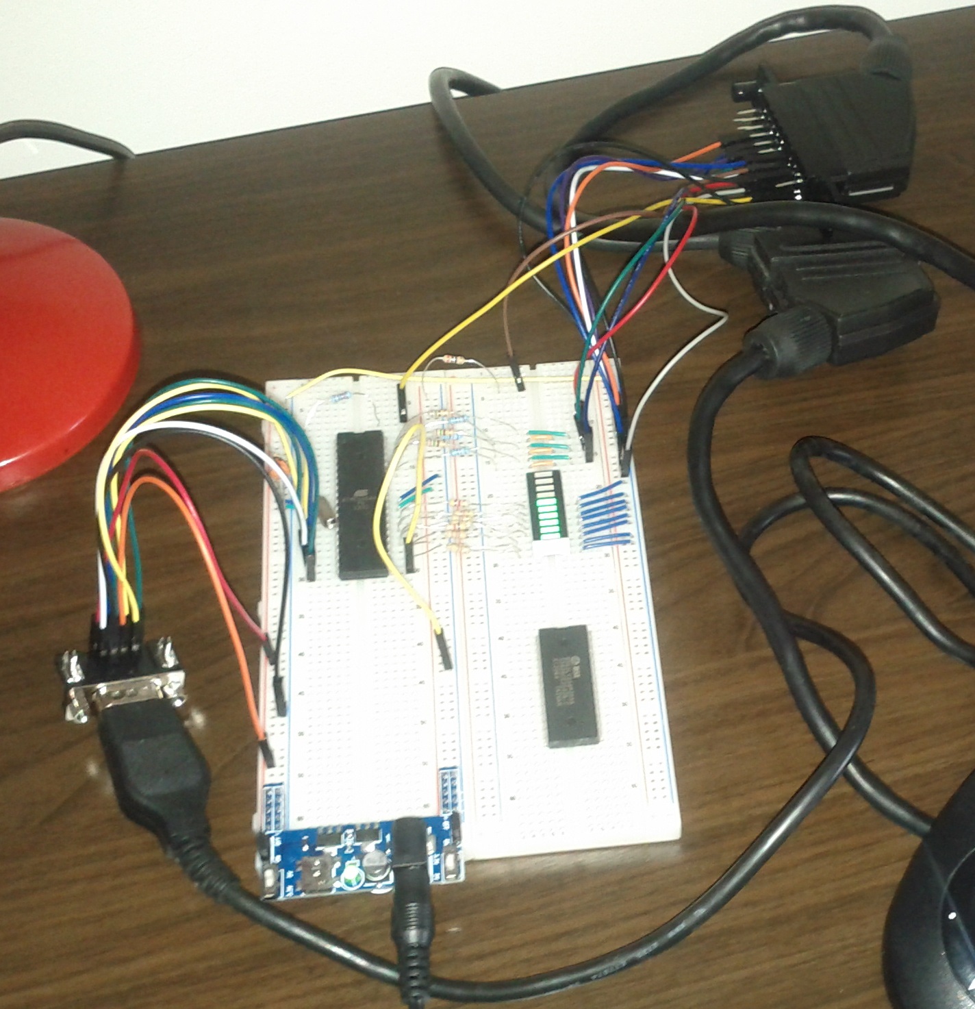
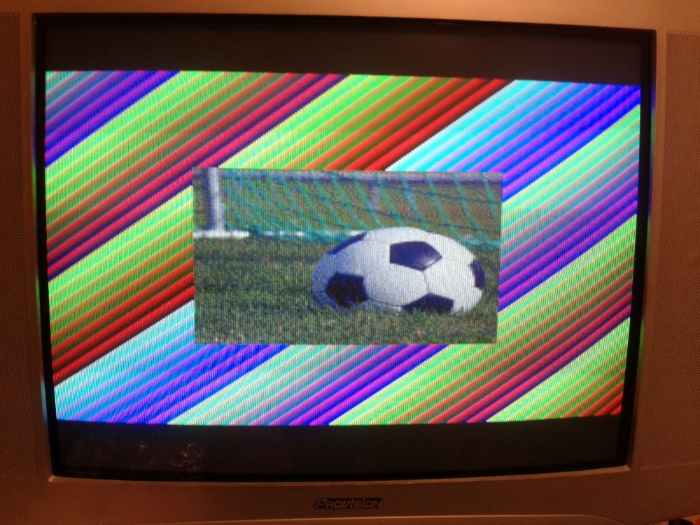
The microcontroller produces 8-bit color (RGB332, 3 bits for red, 3 bits for green and 2 bits for blue) and a passive DAC is used to convert this to analog RGB. Luckily in Portugal one common way to connect an external device to a TV is through a SCART connector and most TVs accept RGB input through SCART.
A proper graphics system
Because I wanted to have a microcontroller only drive the TV signal (I call it the VPU, Video Processing Unit), I decided to use a double-buffer technique.
I had the second microcontroller (PPU, Picture Processing Unit, which is an Atmega1284 also at 20Mhz) generate an image to a RAM chip (VRAM1) while the first one would dump the contents of another RAM chip (VRAM2) to the TV.
After one frame (2 frames in PAL or 1/25th of a second), the VPU switches the RAMs, and dumps the image generated into VRAM1 while the PPU generates an image to VRAM2.
The video board turned out quite complex as I had to use some external hardware to allow for the two micro-controllers to access the same RAM chips and also to speed up the access to RAM that also had to be bit-banged, so I added some 74 series chips such as counters, line selectors, transceivers, etc.
The firmware for VPU and especially the PPU also became quite complex as I had to do extremely performant code to be able to have all the graphical capabilities I wanted, originally it was all done in assembly, later I coded some of it in C.
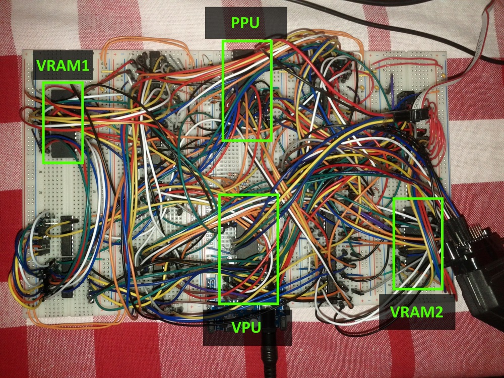
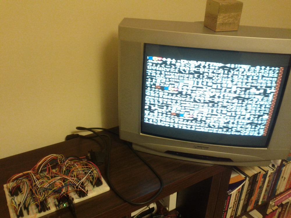
I ended up having the PPU generate a 224x192 pixel image that is then sent to the TV by the VPU. This resolution might seem low, but it is in fact only a bit lower than the consoles mentioned above that usually had resolutions of 256x224 pixels. The lower resolution allowed me to cram more graphical features into the time I had to draw each frame.
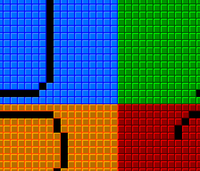
Just like in the old days the PPU has “fixed” capabilities that can be configured. The background that can be rendered is composed of 8x8 pixel characters (sometimes called tiles). This means a screen background has the size of 28x24 tiles.
In order to have per-pixel scrolling and the ability to update the background seamlessly I made it so there are 4 virtual screens each one having 28x24 tiles that are contiguous and wrap around one other:
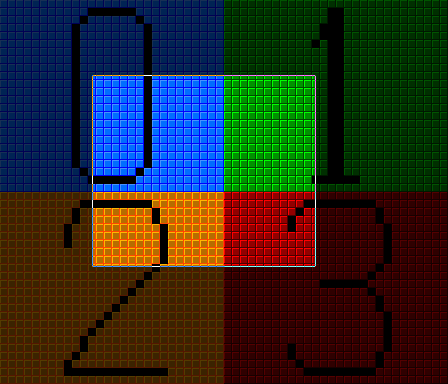
Above the background, the PPU can render 64 sprites that can have a width and height of either 8 or 16 pixels (1, 2 or 4 characters) and can be flipped horizontally or vertically or in both axes.
Also above the background an “overlay” can be rendered, which is a patch composed of 28x6 tiles. This is useful for games that need a HUD and in which the background is scrolling and sprites are being used for other purposes than to show information.
Other “advanced” feature is the ability to scroll the background in different directions in separate lines, this enables games to have effects such as a limited parallax scrolling or split-screen.
And there’s also the attribute table, which is the possibility of giving each tile a value from 0 to 3, and then it’s possible to set all the tiles of a given attribute to a certain tile page or increment their character number. This is useful when there are certain parts of the background that change constantly, the CPU doesn’t need to update each one of the tiles, it only needs to say something like: “all tiles with attribute 1 will increment their character number by 2” (using different techniques, this effect can be seen for example in block tiles with a moving question mark in Mario games or in waterfall tiles that seem to be changing constantly seen in other games).
CPU
After having a functional video board, I started working with the CPU I chose for the console, the Zilog Z80.
One of the reasons I chose the Z80 (other than it just being a cool retro CPU) was because the Z80 has access to a 16bit memory space and a 16bit IO space, something that other similar 8-bit CPUs do not have, such as the famous 6502.
The 6502, for example, only has a 16bit memory space, which means that the whole 16bits were not reserved just for memory but had to be shared between memory access and external device access, such as video, audio, inputs, etc. By having an IO space together with a memory space, I could have the whole of the 16bit memory space reserved for memory (64KB of code and data) and have the IO space for communication with external devices.
I started by connecting the CPU to an EEPROM with some test code and also connecting it via the IO space to a microcontroller I had set up to communicate with a PC via RS232 in order to check if the CPU was functioning well as well as all the connections I was making. This microcontroller (an Atmega324 operating at 20Mhz) was to become the IO MCU (or input/output microcontroller unit), responsible for managing access to the game controllers, SD Card, PS/2 Keyboard and the RS232 communication.
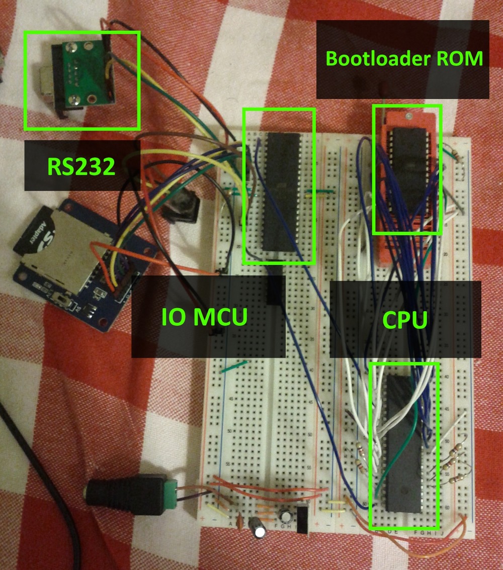
The CPU was then connected to a 128KB RAM Chip, from which 56KB was accessible (this seems like a waste but I could only get either 128KB or 32KB RAM chips). This way the CPUs memory space is composed of 8KB of ROM and 56KB of RAM.
After this I updated the IO MCU’s firmware with the help of this library and added SD Card support.
The CPU was now able to navigate through directories, browse their contents, open and read from files. All this by reading and writing to specific IO space addresses.
Connecting the CPU and the PPU
The next thing I implemented was the interaction between the CPU and the PPU. For this I found “an easy solution” which was to get dual-port RAM (a RAM chip that can be simultaneously connected to two different buses), it saves me from having to place more ICs like line selectors and such and also it makes the accesses to the RAM between both chips virtually simultaneous.
The PPU also communicates with the CPU directly by activating its NMI (non-masking interrupt) every frame. This means the CPU has an interrupt every frame, which makes it valuable for timing and knowing when to update graphics.
Each frame the interaction between CPU, PPU and VPU is as foll
No tags.