Introduction
This is an overview of all the elements which contribute to the dynamic damage system created for Radio Viscera.
I've written this article with a focus on the concepts used rather than a specific language or environment or as a step-by-step guide. The implementation described here was built very specifically for the game I was making, so including the technical minutiae here did not seem helpful. Hopefully some of this information will help you in the development of your own project using whichever engine or environment suits you best.
I've tried to insert as many gifs, screenshots and sounds as I could to keep it from being too dry. The last few sections focus on the (less technical) secondary systems and effects that interact with the destruction and should be a bit more digestible.
This design was built in a custom C++ based game engine which uses an OpenGL renderer and the Bullet Physics SDK.
Index
1. Overview

Figure 1. The central concepts behind the system
The destruction system depends on three elements that work together to present the illusion that a hole is being smashed in a wall:
Parametric geometry
Used to render the damaged walls.
Physics simulation
Controls the collision shapes which make the wall solid, performs raycast queries and helps generate triangulated collision shapes when the wall is damaged.
Render textures
Stores damage data for each wall, which is fed into the geometry shader and also used as the source for generating collision shapes.
2. Initial face generation
Each destructible face is built of three pieces. The first piece is the display mesh which is a parametrically generated plane with position, normal and UV coordinate data. This is used to render the face in-game.
The second piece is the collision shape. This is a static collideable rigid body which is added to the dynamics world of the physics simulation. The shape itself is an identical match for the display mesh and is positioned to sit perfectly over top. In addition to providing the collision that you would expect from a solid wall it also detects damaging raycast queries (see Detecting raycasts).
Figure 2. Initial un-damaged face components (display mesh, collision shape, damage buffer)
The third piece is the damage buffer. This is a 2D render texture used to store the damage state for the face. The dimensions of this texture are calculated to match the size of the face in world space multiplied by a "pixels-per-meter" factor which determines the resolution at which the damage will be stored. In my case I use 48 pixels-per-meter so a wall 4 x 2 meters in worldspace would have a 192 x 96px sized damage buffer. This texture is cleared to RGBA [0,0,0,0].
Until the wall is first damaged these three pieces do not change. The simple planar display mesh allows me to use a standard shader and render the wall like any other entity in the scene until the damage shader is required.
3. Detecting raycasts and applying damage
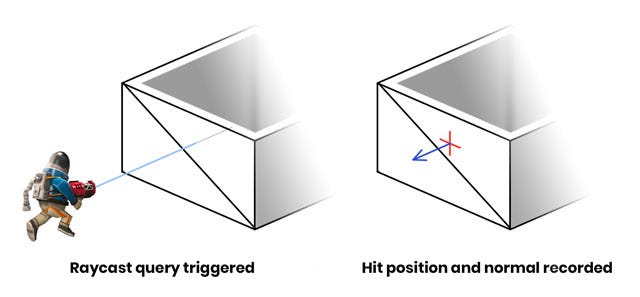
Damage is applied using raycasts. When a weapon is fired a raycast test is performed against all collision bodies in the dynamics world, with the ray originating at the weapon muzzle and extending toward the current aim direction. If the raycast intersects with the collision shape of a damageable face then a hit is registered. The world position and normal direction of the intersection are recorded and forwarded to the damageable face entity so it can record the hit to its damage buffer.

Figure 3. Surface normal of the hit is used for directional effects
To actually apply damage a sprite needs to be drawn to the damage buffer. A black pixel on the damage buffer indicates no damage to that area and a fully white pixel indicates complete destruction of the area. Before the sprite can be drawn I need to calculate where to actually draw onto the damage buffer so it will match the hit location in world space. Barycentric coordinates will be used for this process so I first need to figure out which of the two triangles (that constitute the un-damaged plane collision shape) received the hit.

Figure 4. Steps required to draw the damage onto the buffer
Note: the barycentric method is a leftover from when the system was designed to work with arbitrary triangle meshes. If you're only dealing with flat, rectangular faces this conversion could be simplified.
Finding the correct triangle is done with a ray-triangle intersection test, using the data from the raycast hit. Since there are only two triangles this happens quickly. The destruction world position is then transformed into face-relative local space by multiplying it against the inverse transform of the wall entity. The distances between the hit position and the triangle vertices are calculated and used to generate a UV coordinate which aligns with the damage position on the wall.
![]()
Figure 5. An enlarged and brightened version of the damage sprite
The last step here is to draw the damage sprite to the damage buffer render texture like a stamp. The design of the sprite itself is the result of lots of trial and error to see what kind of shape worked well and had the intended effect (both visually and physically). The rotation of the sprite is randomized and the scale and brightness of the sprite are based on the magnitude of the damage. This allows more powerful hits to make larger holes. The sprite is drawn with additive blending so that successive damage sprites can "build" on each other if applied in the same area.
4. Drawing a damaged wall

Figure 6. Mesh wireframe after tessellation. No damage has been applied.
When an untouched face is damaged for the first time a few things happen. First the display mesh, which up until this point was a two triangle plane, is tessellated. Similar to how the resolution of the damage buffer is calculated, there is a mesh density factor which describes "faces-per-meter". I use a value of 6, so my 4 x 2m wall results in a mesh that measures 24 x 12 square sections (576 triangles). The blue channel of the vertex color is used as a boolean value to mark which vertices are on the outermost edges of the plane mesh. This allows me to extrude those vertices in the geometry shader to create the wall thickness you see along the top edge.
Once damage has been applied, the face is flagged and starts to draw using a special damage shader. This shader samples from the damage buffer and uses a geometry stage to cull any faces that are fully damaged and construct a solid tapered edge at the borderline of the damaged area.

Figure 7. Visual representation of the two UV sets (lower) with the textures they sample (upper)
The wall geometry needs to have tiling UVs so the square wall display texture can repeat on long sections without stretching. However, the damage buffer requires unique UVs that map 1-to-1 with the wall geometry so a second set of UVs are generated and stored in the red and green channels of the vertex color. This way each vertex of the wall is mapped to a unique space on the damage buffer.
This next bit is the part where I try to describe a shader using words. If you prefer to just read the pseudocode, scroll down a bit further.
In the geometry shader each triangle of the mesh is processed independently. The UVs from the three vertices of each triangle are sampled from the damage buffer to determine if any of them should be fully discarded. If all three vertices are damaged beyond the threshold value then the entire triangle is discarded and the shader returns.
If none of the triangle vertices have any damage then the triangle should just be drawn normally. These triangles actually need to be drawn twice: once regularly and then again extruded inwards with the normal and winding order inverted. This makes the wall look double-sided and gives it its thickness. Before finishing, the shader will also check if any of these vertices are edge vertices via the vertex color attribute we used earlier. If it is an edge vertex the shader will generate flat geometry to cover the top edge which masks the hollow area between the two wall faces.
The last case is the most involved. In this case one or more of the three vertices has a damage value greater than 0 but below the threshold of "fully damaged". The position of the damaged vertex is transformed so the more damage a vertex has the more it will be pushed inward, both into the wall and toward it's neighbour vertices. This transform is applied to the original vertices as well as the inverted "inner wall" vertices. The resulting effect is a polygonal edge that shrinks and grows closer together as more damage is applied, making the wall geometry thinner and thinner until


