The following article has originally been posted here: http://blog.three-eyed-games.com/2018/05/03/gpu-ray-tracing-in-unity-part-1/
These are truly exciting times for ray tracing. Latest advances like AI-accelerated denoising, Microsoft announcing native support in DirectX 12 and Peter Shirley releasing his books on a pay what you want basis make it look like ray tracing finally has the chance to become acceptable at court. It might be too early to speak of the beginning of a revolution, but it sure is a good idea to learn and build knowledge around the topic.
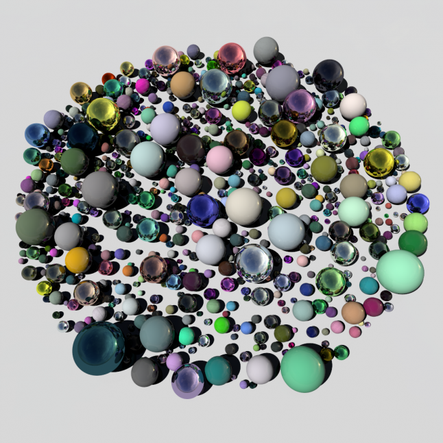
In this article, we're going to write a very simple ray tracer from scratch using compute shaders in Unity. The languages we will use are C# for the scripts and HLSL for the shaders. Follow along and you will end up with a rendering like this:
Ray tracing theory
I would like to start by quickly reviewing the basic ray tracing theory. If you are familiar, please feel free to skip ahead.
Let's think about how photographs emerge in the real world – highly simplified, but for the purpose of rendering this should be fine. It all starts with a light source emitting photons. A photon flies in a straight line until it hits a surface, at which point it is reflected or refracted and continues its journey minus some energy that has been absorbed by the surface. Eventually, some photons will hit the camera's image sensor which in turn produces the resulting image. Ray tracing basically simulates these steps to create photorealistic images.
In practice, only a tiny fraction of the photons emitted by a light source will ever hit the camera. Therefore, applying the principle of Helmholtz reciprocity, calculations are commonly reversed: Instead of shooting photons from light sources, rays are shot from the camera into the scene, reflected or refracted and eventually hit a light source.
The ray tracer we are going to build is based on a 1980 paper by Turner Whitted. We will be able to simulate hard shadows and perfect reflections. It will also serve as a basis for more advanced effects like refraction, diffuse global illumination, glossy reflections and soft shadows.
Basic setup
Let's start by creating a new Unity project. Create a C# script RayTracingMaster.cs and a compute shader RayTracingShader.compute. Fill the C# script with some basic code:
using UnityEngine;

public class RayTracingMaster : MonoBehaviour
{
    public ComputeShader RayTracingShader;

    private RenderTexture _target;

    private void OnRenderImage(RenderTexture source, RenderTexture destination)
    {
        Render(destination);
    }

    private void Render(RenderTexture destination)
    {
        // Make sure we have a current render target
        InitRenderTexture();

        // Set the target and dispatch the compute shader
        RayTracingShader.SetTexture(0, "Result", _target);
        int threadGroupsX = Mathf.CeilToInt(Screen.width / 8.0f);
        int threadGroupsY = Mathf.CeilToInt(Screen.height / 8.0f);
        RayTracingShader.Dispatch(0, threadGroupsX, threadGroupsY, 1);

        // Blit the result texture to the screen
        Graphics.Blit(_target, destination);
    }

    private void InitRenderTexture()
    {
        if (_target == null || _target.width != Screen.width || _target.height != Screen.height)
        {
            // Release render texture if we already have one
            if (_target != null)
                _target.Release();

            // Get a render target for Ray Tracing
            _target = new RenderTexture(Screen.width, Screen.height, 0,
                RenderTextureFormat.ARGBFloat, RenderTextureReadWrite.Linear);
            _target.enableRandomWrite = true;
            _target.Create();
        }
    }
}
The OnRenderImage function is automatically called by Unity whenever the camera has finished rendering. To render, we first create a render target of appropriate dimensions and tell the compute shader about it. The 0 is the index of the compute shader's kernel function – we have only one.
Next, we dispatch the shader. This means that we are telling the GPU to get busy with a number of thread groups executing our shader code. Each thread group consists of a number of threads which is set in the shader itself. The size and number of thread groups can be specified in up to three dimensions, which makes it easy to apply compute shaders to problems of either dimensionality. In our case, we want to spawn one thread per pixel of the render target. The default thread group size as defined in the Unity compute shader template is [numthreads(8,8,1)], so we'll stick to that and spawn one thread group per 8×8 pixels. Finally, we write our result to the screen using Graphics.Blit.
Let's give it a try. Add the RayTracingMaster component to the scene's camera (this is important for OnRenderImage to be called), assign your compute shader and enter play mode. You should see the output of Unity's compute shader template in the form of a beautiful triangle fractal.
Camera
Now that we can display things on screen, let's generate some camera rays. Since Unity gives us a fully working camera, we will just use the calculated matrices to do this. Start by setting the matrices on the shader. Add the following lines to the script RayTracingMaster.cs:
private Camera _camera;

private void Awake()
{
    _camera = GetComponent();
}

private void SetShaderParameters()
{
    RayTracingShader.SetMatrix("_CameraToWorld", _camera.cameraToWorldMatrix);
    RayTracingShader.SetMatrix("_CameraInverseProjection", _camera.projectionMatrix.inverse);
}
Call SetShaderParameters from OnRenderImage before rendering.
In the shader, we define the matrices, a Ray structure and a function for construction. Please note that in HLSL, unlike in C#, a function or variable declaration needs to appear before it is used. For each screen pixel's center, we calculate the origin and direction of the ray, and output the latter as color. Here is the full shader:
#pragma kernel CSMain

RWTexture2D Result;
float4x4 _CameraToWorld;
float4x4 _CameraInverseProjection;

struct Ray
{
    float3 origin;
    float3 direction;
};

Ray CreateRay(float3 origin, float3 direction)
{
    Ray ray;
    ray.origin = origin;
    ray.direction = direction;
    return ray;
}

Ray CreateCameraRay(float2 uv)
{
    // Transform the camera origin to world space
    float3 origin = mul(_CameraToWorld, float4(0.0f, 0.0f, 0.0f, 1.0f)).xyz;

    // Invert the perspective projection of the view-space position
    float3 direction = mul(_CameraInverseProjection, float4(uv, 0.0f, 1.0f)).xyz;
    // Transform the direction from camera to world space and normalize
    direction = mul(_CameraToWorld, float4(direction, 0.0f)).xyz;
    direction = normalize(direction);

    return CreateRay(origin, direction);
}

[numthreads(8,8,1)]
void CSMain (uint3 id : SV_DispatchThreadID)
{
    // Get the dimensions of the RenderTexture
    uint width, height;
    Result.GetDimensions(width, height);

    // Transform pixel to [-1,1] range
    float2 uv = float2((id.xy + float2(0.5f, 0.5f)) / float2(width, height) * 2.0f - 1.0f);

    // Get a ray for the UVs
    Ray ray = CreateCameraRay(uv);

    // Write some colors
    Result[id.xy] = float4(ray.direction * 0.5f + 0.5f, 1.0f);
}
Try rotating the camera in the inspector. You should see that the 'colorful sky' behaves accordingly.
Now let's replace the colors with an actual skybox. I am using HDRI Haven's Cape Hill in my examples, but you can of course use any one that you like. Download and drop it into Unity. In the import settings, remember to increase the maximum resolution if you downloaded a higher resolution than 2048. Now add a public Texture SkyboxTexture to the script, assign your texture in the inspector and set it on the shader by adding this line to the SetShaderParameters function:
RayTracingShader.SetTexture(0, "_SkyboxTexture", SkyboxTexture);
In the shader, define the texture and a corresponding sampler, and a π constant that we'll use in a minute:
Texture2D _SkyboxTexture;
SamplerState sampler_SkyboxTexture;
static const float PI = 3.14159265f;
Now instead of writing the direction as color, we'll sample the skybox. To do this, we transform our cartesian direction vector to spherical coordinates and map this to texture coordinates. Replace the last bit of the CSMain by this:
// Sample the skybox and write it
float theta = acos(ray.direction.y) / -PI;
float phi = atan2(ray.direction.x, -ray.direction.z) / -PI * 0.5f;
Result[id.xy] = _SkyboxTexture.SampleLevel(sampler_SkyboxTexture, float2(phi, theta), 0);
Tracing
So far so good. Now we're getting to the actual tracing of our rays. Mathematically, we will calculate the intersection between our ray and our scene geometry, and store the hit parameters (position, normal and distance along the ray). If our ray hits multiple objects, we will pick the closest one. Let's define the struct RayHit in the shader:
struct RayHit
{
    float3 position;
    float distance;
    float3 normal;
};

RayHit CreateRayHit()
{
    RayHit hit;
    hit.position = float3(0.0f, 0.0f, 0.0f);
    hit.distance = 1.#INF;
    hit.normal = float3(0.0f, 0.0f, 0.0f);
    return hit;
}
Commonly, scenes are comprised of many triangles, but we will start simple: intersecting an infinite ground plane and a handful of spheres!
Ground Plane
Intersecting a line with an infinite plane at y=0 is pretty simple. We only accept hits in positive ray direction though, and reject any hit that is not closer than a potential previous hit.
By default, parameters in HLSL are passed by value and not by reference, so we would only be able to work on a copy and not propagate changes to the calling function. We pass RayHit bestHit with the inout qualifier to be able to modify the original struct. Here's the shader code:
void IntersectGroundPlane(Ray ray, inout RayHit bestHit)
{
    // Calculate distance along the ray where the ground plane is intersected
    float t = -ray.origin.y / ray.direction.y;
    if (t > 0 && t < bestHit.distance)
    {
        bestHit.distance = t;
        bestHit.position = ray.origin + t * ray.direction;
        bestHit.normal = float3(0.0f, 1.0f, 0.0f);
    }
}
To use it, let's add a framework Trace function (we will extend it in a minute):
RayHit Trace(Ray ray)
{
    RayHit bestHit = CreateRayHit();
    IntersectGroundPlane(ray, bestHit);
    return bestHit;
}
Furthermore, we need a basic shading function. Again, we pass the Ray with inout - we will modify it later on when we talk about reflection. For debug purposes, we return the normal if geometry was hit, and fall back to our skybox sampling code otherwise:
float3 Shade(inout Ray ray, RayHit hit)
{
    if (hit.distance < 1.#INF)
    {
        // Return the normal
        return hit.normal * 0.5f + 0.5f;
    }
    else
    {
        // Sample the skybox and write it
        float theta = acos(ray.direction.y) / -PI;
        float phi = atan2(ray.direction.x, -ray.direction.z) / -PI * 0.5f;
        return _SkyboxTexture.SampleLevel(sampler_SkyboxTexture, float2(phi, theta), 0).xyz;
    }
}
We will use both functions down in CSMain. Remove the skybox sampling code if you haven't already, and add the following lines to trace the ray and shade the hit:
// Trace and shade
RayHit hit = Trace(ray);
float3 result = Shade(ray, hit);
Result[id.xy] = float4(result, 1);
Sphere
A plane is not the most exciting thing in the world, so let's add a sphere rightaway. The math for a line-sphere intersection can be found on Wikipedia. This time there can be two ray hit candidates: the entry point p1 - p2, and the exit point p1 + p2. We will check the entry point first, and only use the exit point if the other one is not valid. A sphere in our case is defined as a float4 comprised of position (xyz) and radius (w). Here's the code:
void IntersectSphere(Ray ray, inout RayHit bestHit, float4 sphere)
{
    // Calculate distance along the ray where the sphere is intersected
    float3 d = ray.origin - sphere.xyz;
    float p1 = -dot(ray.direction, d);
    float p2sqr = p1 * p1 - dot(d, d) + sphere.w * sphere.w;
    if (p2sqr < 0)
        return;
    float p2 = sqrt(p2sqr);
    float t = p1 - p2 > 0 ? p1 - p2 : p1 + p2;
    if (t > 0 && t < bestHit.distance)
    {
        bestHit.distance = t;
        bestHit.position = ray.origin + t * ray.direction;
        bestHit.normal = normalize(bestHit.position - sphere.xyz);
    }
}
To add a sphere, just call this function from Trace, for example: