(This article was also posted at https://spacemoguls.com/space-moguls-map-screen-retrospective/)
This is a technical article describing the development of the map screen of Space Moguls for Commodore 64 and published by Protovision. The article is not reasoning why I develop Commodore 64 games, but a technical and design deep dive into the map screen of the title. There are no code snippets in this article.
Space Moguls is a 2018 four player strategy game inspired by M.U.L.E. that was released 35 years earlier in 1983 by Ozark Softscape and published by then just-founded Electronic Arts. Both games are based on taking turns claiming land, generating items and trading between players and the store with the goal of having the most wealth at the end.
To learn more about the game feel free to look over the Player’s Guide here: space-moguls-players-guide
One aspect where Space Moguls differs from M.U.L.E. is the map screen which instead of being two color black on white uses the full 16 color palette the computer is capable of, This was the first system created for the game and contains several features that may not be obvious while playing the game.
The map is procedurally generated at the start of the game, and much of the map is covered in fog so that the final map is not known in the beginning. Since each land cell type produces different amounts of each item type this means players may change their strategy as the game reveals more of the map.
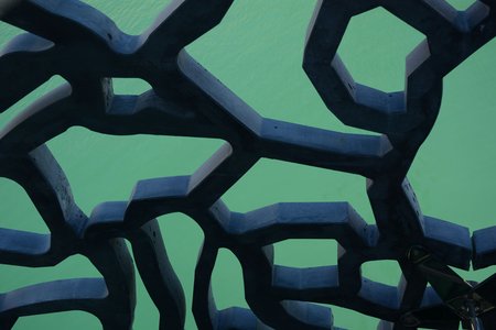
This is how the final map screen looks like during the Production stage, one of the seven stages of each turn:

The end result of the Map Screen during the Production Phase 4 rounds into a game.
Going back to the planning, here is the full on-paper map design of the game. For a short while the town covered three land cells, but as seen above the town sits in land cell #42. This picture was printed on paper and all the subsequent design was based on notes written over it. This is not its final form, but a readable capture from mid-development!

Design notes, this page is the entire documented map design of Space Moguls
Cell layout planning
One early decision was to use a hex grid for the map. This required some planning for hardware built for 40 by 25 characters of 8 by 8 pixels. In multi-color mode the pixels are also double width, meaning each pair of pixels share the same color.
The first design question was what is the best orientation for the hex grid?

The noticeable difference between A and B in the image above is that the hex cells are larger in A allowing more art detail per cell, but the slanted edges look worse due to the double width pixels. This stage of just drawing different grid layouts and seeing how each compared to the rest took quite a bit of time and these examples are just the most workable ones I came up with.
This choice ended up with B as the winner because I could fit exactly 10 hex cells horizontally on even lines and 9 on odd lines, and 8 rows perfectly filling 40 by 25 character cells! Of course this didn’t leave any room for a game HUD but that’s a different problem that future me will have to deal with.
Dealing with overlaps
Commodore 64 multicolor bitmap mode uses 3 out of 16 colors plus a shared background color for each screen character (8×8 pixels). Below is an example of one screen character with the background color black, and custom colors dark gray, mid gray and light gray.

An example of one bitmap character (8×8 pixels with double width to specify multicolor)
The top and bottom of the hex cells the screen characters are shared with neighboring cells. This means those screen characters need to share the same 3 colors + background, which is too restrictive in the source art.
Being able to use all 3 colors for each 8×8 character in the hex cell art helps add color and distinctiveness to each hex cell type so the best solution is to accept drawing cells in overlapping characters with color remapping.
The simplest useful remapping is just counting how many pixels of each color is used in each 8×8 cell (out of 32 double pixels) and pick the 3 most used colors. Pixels with colors that are discarded are replaced by looking up the closest match in a table.
Mixing characters and remapping colors is not a fast rendering approach on a 6502 series CPU running at 1 MHz, but it isn’t unreasonable. Anytime you draw in bitmap mode you’re not updating every frame (unless doing extreme speed-coding!)
But why stop at hex cells with straight edges, since rendering hex cells is so complex anyway? Drawing outside the lines allows for a sense of ground height, like the trees in the forest cell, cactuses in the desert cell or mountain peaks in the mountain cell.

The various types of hex cells in Alia Terra of Space Moguls, from left to right: Plains, Forest, Desert, Mountains, Steppe, Marsh and Lake.
This is what the source art of the desert land type looks like

In the desert cell example above, to the left is the art made up of 4×5 characters (8×8 pixels). The middle white shape is the background mask, these are the parts of the art that are drawn on top of the land cells above. To the right is the overlay mask which represents pixels drawn on top of other cells background and river cells.
The rendering is done one 8×8 screen character at a time so if just part of the land cell needs to redraw only the characters that actually change needs to redraw.
River Cells
Another early design decision was that a river crosses the map between the top and the bottom. Land cells with a river has a bonus for producing food, but a negative effect for most other kinds of items. The river can be seen both in the map screenshot and the paper design above and rendering the river layer fits easily into rendering the land cell layers. It is nearly essential to capture a good river/plains cell early in the game to have a good supply of food throughout the game.

Each river cell has a background and a draw mask.
There are six sides to each cell which results in 13 combinations of land cell inlet and outlet. The direction of the river doesn’t matter.
Step by step Land Cell rendering
For the example below I’m showing a desert cell neighboring a lake cell and with a river running through it. It would be unlikely to appear in the game in this configuration but it is easier to see the river and forest/lake cells being drawn.

A step by step drawing of all the land cell layers except gameplay
The steps represented by the image above are:
Draw background bottom parts of the cells above left and above right
Draw the cell itself with the background mask
Draw the top parts of the cells below left and right with their background mask
Draw the river if one intersects the Land Cell
Draw the cell itself again with its overdraw mask
Draw the top parts of the cells below left and right with their overdraw mask
On top of the map the Installed Droid and production tabs can be drawn.
The final color remapping back to 3 colors + background color for each 8×8 pixel character is not shown here.
Owned Land Cells
 As soon as a player claims a Land Cell a house icon using that player’s color is drawn into the cell to mark it as occupied. This happens during the Land Grant or the Land Auction stages, and in rare cases a Global Event can award one player an extra Land Cell.
The icons above represent:
Unassigned owned land (House)
Ore mining droid
Food producing droid (Land)
Food producing droid (Lake)
Materials producing droid